Key Takeaways
- Start with duty, environment and failure cost — not diameter. The rest of the build follows from those three.
- Check the rpm before you check the price. Roller speed, calculated from belt speed and diameter, is the number that quietly decides bearing life.
- Choose the seal by contaminant, not by habit: dry dust at speed → labyrinth; washdown, slurry or rain → contact.
- A seized roller costs far more than the roller. Belt cover damage, spillage and access time on a long overland run dwarf the component price.
- Write tube wall thickness into the enquiry in millimetres, not as a range — it is the most common hidden downgrade in a cheap quotation.
Why the Usual Way of Specifying Idlers Fails
A maintenance team replaces a failed roller. They measure it, find a drawing, and order "the same again, please". Six months later the same position fails again. The roller was not wrong because of its size — it was wrong because nobody asked what it was dying of.
An idler is a sealed rotating assembly running in dust, water, heat or all three, for years, unattended. Every choice inside it — wall thickness, bearing clearance, seal geometry, shaft material — is a trade against one specific failure mechanism. Change the mechanism and the correct build changes with it.
Question One: What Is the Duty?
Duty is not just tonnage. It is tonnage, belt speed, loading conditions and where in the conveyor the roller sits.
| Position | What it actually sees | What the build needs |
|---|
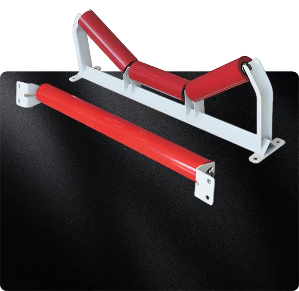
| Carrying (troughing) | Continuous load, material impact at transfer, three-roll load sharing | Wall thickness and bearing class for the radial load; correct trough angle |
| Impact (loading point) | Drop energy from lump material, belt cover damage risk | Rubber rings or discs to absorb energy; closer spacing |
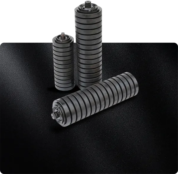
| Return | Belt weight only, but carry-back and material build-up | Self-cleaning geometry (spiral, rubber disc) where material is sticky |
| Training / self-aligning | Lateral belt wander | Friction or pivoting frame response — and correct placement, not more of them |
Two conveyors with identical tonnage can need completely different idlers if one is loaded from a chute at four metres and the other from a feeder at half a metre. Drop height is a specification input.
Question Two: What Is the Environment Doing to It?
This is the question that decides the seal — and the seal is what actually determines service life in the field.
- Dry, fine dust at speed (cement, fly ash, grain): the enemy is ingress plus heat. A multi-stage labyrinth seal runs cool and keeps dust out without contact friction.
- Washdown, rain or slurry (port, wash plant, fertiliser): the enemy is water. A contact seal keeps water out but generates friction and heat, so it belongs at lower speeds.
- High temperature (cement clinker, sinter, coke): seals and grease have temperature ceilings long before steel does. Specify the temperature, not just "hot".
- Corrosive or coastal (port terminals, chemical): coating, galvanising and material choice matter as much as the seal.
Running a contact seal at 4 m/s in a dry cement plant is a common and expensive mismatch: it heats, the grease degrades, and the bearing fails early in an environment where a labyrinth would have lasted years.
Question Three: What Does Failure Actually Cost?
This is the question that turns a specification from a purchase into an engineering decision.
On a short in-plant conveyor, a failed roller is a nuisance: swap it at the next shutdown. On a 3 km overland conveyor running 20 hours a day, the same failure costs a crew mobilisation, access time along the gallery, belt cover damage from the seized shell, spillage clean-up, and — if the belt is the production bottleneck — lost throughput.
When the cost of failure is high, the specification should move up, not down: thicker wall, higher-grade bearing, better seal, closer inspection interval. The component price difference is small against the avoided outage.
The Check Most Spec Sheets Skip: Roller rpm
Bearing life is governed by speed as well as load. Roller speed follows directly from belt speed and diameter:
rpm = (belt speed in m/min) ÷ (π × roller diameter in m)
500 rpm is the CEMA basis speed — the speed at which idler load ratings and rated life are normally published, and therefore the design target. The catalogue figure is the L10 life at 500 rpm; it is not a figure that holds at any speed. 600 rpm is the general engineering limit in both Chinese and international idler standards and design handbooks — past it, rotational resistance climbs sharply and service life falls away. 750 rpm is a ceiling only for specific standards and special designs, BOS 613 among them, and never a general target.
The matrix below turns that formula into a specification table. Read down to your belt speed, move right to the first green cell, and you have the minimum diameter for that duty:
| Belt speed | 63.5 mm | 76 mm | 89 mm | 108 mm | 133 mm | 159 mm | 194 mm | 219 mm |
|---|
| 1 m/s | 301 | 251 | 215 | 177 | 144 | 120 | 98 | 87 |
| 1.5 m/s | 451 | 377 | 322 | 265 | 215 | 180 | 148 | 131 |
| 2 m/s | 602 | 503 | 429 | 354 | 287 | 240 | 197 | 174 |
| 2.5 m/s | 752 | 628 | 536 | 442 | 359 | 300 | 246 | 218 |
| 3 m/s | 902 | 754 | 644 | 531 | 431 | 360 | 295 | 262 |
| 3.5 m/s | 1053 | 880 | 751 | 619 | 503 | 420 | 345 | 305 |
| 4 m/s | 1203 | 1005 | 858 | 707 | 574 | 480 | 394 | 349 |
| 5 m/s | 1504 | 1256 | 1073 | 884 | 718 | 601 | 492 | 436 |
| 6 m/s | 1805 | 1508 | 1288 | 1061 | 862 | 721 | 591 | 523 |
≤ 500 rpm — at or below the CEMA rating basis500–600 rpm — above the basis, within the general limit600–750 rpm — past the general limit; special design only> 750 rpm — above any standard limit
Rotational speed in rpm, from rpm = belt speed × 60 ÷ (π × diameter); rounded to the nearest rpm.
Two things follow from this. A diameter that is generous at 1.5 m/s is badly over-speed at 4 m/s — which is why copying the diameter from an older, slower line is the single most common over-speed mistake. And a 6 m/s conveyor is served by no diameter up to 219 mm within the 500 rpm basis speed: that duty needs a larger roller, a lower belt speed, or a deliberate trade-off against bearing life, and only your project can say which of those can actually change.
Minimum diameter by belt speed
If you would rather not read the matrix, this is the same calculation reduced to a single recommendation per belt speed:
| Belt speed | Minimum diameter — ≤500 rpm (CEMA basis) | Minimum diameter — ≤600 rpm (general limit) |
|---|
| 1 m/s | 63.5 mm (301 rpm) | 63.5 mm (301 rpm) |
| 1.5 m/s | 63.5 mm (451 rpm) | 63.5 mm (451 rpm) |
| 2 m/s | 89 mm (429 rpm) | 76 mm (503 rpm) |
| 2.5 m/s | 108 mm (442 rpm) | 89 mm (536 rpm) |
| 3 m/s | 133 mm (431 rpm) | 108 mm (531 rpm) |
| 3.5 m/s | 159 mm (420 rpm) | 133 mm (503 rpm) |
| 4 m/s | 159 mm (480 rpm) | 133 mm (574 rpm) |
| 5 m/s | 194 mm (492 rpm) | 194 mm (492 rpm) |
| 6 m/s | none up to 219 mm | 194 mm (591 rpm) |
A ø108 mm roller under a 3.5 m/s belt turns at roughly 620 rpm — past the 600 rpm general limit. Step the roller up to ø133 mm and the same belt runs it at about 500 rpm, the CEMA basis speed, for a marginal change in roller cost. On a line that has been uprated, the diameter on the old drawing is the last number you should trust.
Still worth adding: one thing would make this page impossible for a competitor to match — photographs of failed rollers showing the grease condition and race appearance described in our
failure analysis. Buyers cannot get that from a catalogue.
L10 Life and the CEMA Classes: What the Rating Actually Promises
The question every buyer asks — how long will it last? — is answered by the CEMA class. The standard ties an idler's load capacity to a minimum L10 life, and it sets one common basis for that rating: 500 rpm. The class on your specification is therefore a statement about both the load the roller can carry and the life it is expected to give at that speed.
| CEMA class | Minimum L10 life at 500 rpm | Typical application |
|---|
| CEMA B | 30,000 hours | Light to medium load, conventional duty |
| CEMA C | 30,000 hours | Medium load, moderate belt speed |
| CEMA D | 60,000 hours | Heavy load; critical process, or hard-to-access positions |
| CEMA E / F | 60,000 hours | Very heavy load, high-impact duty |
Minimum L10 life figures at the 500 rpm basis speed. The class also sets bearing series and shaft-end requirements — it is not a statement about life alone.
Two things this table is easy to misread
First, it is a floor, not a prediction. The class states the life the roller is designed to achieve at least at 500 rpm; a well-built roller in that class will often exceed it. Two rollers in the same class can differ substantially in real service life, because class fixes the minimum and the build decides everything above it.
Second, life in hours moves with speed. Bearing life is fundamentally published as L10 revolutions, and hours are those revolutions divided by rotational speed. At constant load that makes the relationship direct: run the roller slower than the basis speed and you stretch the life in proportion; run it faster and you shorten it. A roller at 350 rpm can be expected to give roughly 500 ÷ 350 ≈ 1.4 times the published figure, and the same roller pushed past 600 rpm gives proportionally less — which is why an over-speed roller fails long before its class would suggest.
The practical consequence is that the two specification questions belong together: check the rpm first, then read the CEMA class. A CEMA D roller run past its speed limit will not deliver its 60,000 hours. The class promises life at the basis speed, not at any speed.
What to ask when a quotation names a CEMA class
- "At what speed is that rating?" The answer should be 500 rpm. Any other answer means the class is being quoted loosely, and the life figure behind it does not mean what you think.
- "Which class am I being offered, and what is the L10 behind it?" A quotation that gives a bearing size and a price but no class has not told you the life you are buying.
- "Does the class match my duty — or my access?" A critical or hard-to-reach flight can justify CEMA D even when the load is only medium. Where a change-out means stopping the line, the cost of access, not the load, decides the class.
Then, and Only Then: Diameter, Wall, Bearing, Seal
| Parameter | What it decides | How to specify it |
|---|
| Roller diameter | Bearing speed, belt support spacing, load capacity | From belt width, speed and trough set — check rpm, not habit |
| Tube wall thickness | Shell life under abrasion and impact | In mm, stated as a value not a range; the #1 hidden downgrade |
| Shaft | Deflection under load — deflection kills bearings | Material and diameter; cold-drawn 45# is our standard |
| Bearing | Life under load and speed | Named brand (HRB / ZWZ / SKF / FAG) and clearance class — C3 default, C4 for hot duty |
| Grease | Whether the lubrication survives the duty temperature | Continuous service range, not dropping point: −40 °C to +120 °C standard, to +160 °C for clinker duty |
| Seal | Whether the bearing reaches its design life at all | By contaminant: labyrinth for dry/fast, contact for wet/slow |
| Runout | Vibration, belt tracking, noise | Total indicator reading in mm, measured after assembly |
Bearing and Grease: The Two Lines a Quotation Usually Leaves Out
Most quotations state the bearing as a single line — 6205-2RS — and stop there. That one line hides the two decisions that determine whether a roller runs 8,000 hours or 40,000. Below is what we build to, and the reasoning behind each choice, so you can put the same numbers into your own specification.
Bearing brand: four options, chosen by duty and by who signs the PO
| Brand | When we quote it | Why it is chosen |
|---|
| HRB (Harbin Bearing) | Standard build — general-duty conveyors, bulk and repeat orders | Broad size coverage, stable supply, and the best cost-per-hour on normal duty. The default unless something in the duty says otherwise. |
| ZWZ (Wafangdian Bearing) | Standard build — mining duty, larger roller series, higher load ratings | Stronger coverage in the heavier series that mining conveyors use, with the same supply stability. |
| SKF | When the end user or the EPC names it; critical or high-speed positions | Named-specification projects, and sites where the maintenance team already standardises on SKF and stocks it. |
| FAG (Schaeffler) | Same — named-specification projects, European-owned or European-engineered sites | Where the plant's own bearing standard is Schaeffler, or the EPC's specification schedule names it. |
We build to the named brand rather than to "a well-known brand", because a substitution at assembly time is invisible on the drawing and impossible to audit later. If your specification names a brand, say so on the PO.
Internal clearance: C0, C3 or C4
Radial internal clearance is the free play inside the bearing before it is fitted. It matters more on a conveyor than almost anywhere else, because two things eat into it before the roller carries a single tonne: the interference fit on the shaft, and running warmth. Fit a standard-clearance bearing into a tight housing on a warm, fast conveyor and it starts life already partly preloaded.
| Class | What it means | When to specify it |
|---|
| C0 (normal) | Standard radial clearance as supplied | Only on short, slow, cool conveyors with a light fit. On a warm or fast flight it leaves no margin for fit and thermal growth — this is the class that produces the preload failure. |
| C3 | Greater than normal | The conveyor default. Absorbs the interference fit and normal running temperature without going into preload. If your specification does not name a class, this is the one that should have been meant. |
| C4 | Greater than C3 | High-ambient duty (cement clinker, sinter, coke), a wide seasonal temperature swing, a heavy press fit, or a long overland conveyor in a hot climate — anywhere the bearing sees more thermal growth than C3 can absorb. |
Clearance values are defined by bore diameter, not by bearing designation alone — under ISO 5753-1, and GB/T 4604 in China. If a spec sheet names a class but not a bore size, ask for the actual figure in microns.
Grease: type, and the temperature range it is actually rated for
| Grease | Continuous service range | Specified for |
|---|
| General-purpose lithium, No. 2 | −20 °C to +120 °C | Standard build on normal-duty conveyors — indoor or moderate climate, continuous running |
| Low-temperature lithium / semi-synthetic | −40 °C to +120 °C | Our standard charge. Cold-climate and winter outdoor duty — Russia, Kazakhstan, northern China — and any line that starts cold |
| Lithium complex / polyurea, high temperature | −20 °C to +160 °C | Clinker, sinter, coke and other high-ambient duty, where a standard lithium charge would degrade long before the steel does |
The number that matters is the continuous service ceiling, not the dropping point. A grease that survives 180 °C on a test rig may still break down at 120 °C in continuous running, and on a sealed-for-life roller the charge has to last the whole intended service life — which is a function of speed and temperature together.
When a bearing does fail early, the failed roller itself tells you which of these choices was wrong — we work through that in why conveyor idler bearings seize before they wear out.
Frequently Asked Questions
How do I know if my roller diameter is too small?
Calculate the rpm from belt speed and diameter. If it sits above the practical limit for your bearing and duty, the bearing will fail long before the shell wears. One diameter step usually buys several times the service life.
Is 35° always the right trough angle?
35° is the general default because it balances capacity against belt stress. 20° suits older or narrow installations and fragile material; 45° suits high tonnage and long overland runs where spillage control matters more than belt fatigue.
Labyrinth seal or contact seal?
Choose by contaminant. Dry dust at speed favours labyrinth — low friction, low heat, long life. Washdown, slurry or rain favours contact. Running a contact seal at high speed generates heat and shortens life.
Why do two quotations for the same idler differ by 30%?
Usually tube wall thickness, bearing brand and clearance class, seal construction and shaft material. Ask for all four in writing, with wall thickness in millimetres rather than a range.
What is the real cost of a failed idler?
The roller is the smallest part of it. A seized roller damages belt cover, sheds material, creates housekeeping and fire risk, and on a long overland conveyor the access time alone exceeds the component price many times over.
What does a CEMA class actually guarantee?
A minimum L10 life at the 500 rpm basis speed. CEMA B and C carry a 30,000 hour minimum; CEMA D and CEMA E/F a 60,000 hour minimum. It is a floor rather than a prediction — the class fixes the minimum and the build decides everything above it — and it is tied to the basis speed, so a roller run past 600 rpm will not deliver the figure its class promises.